Developer Insights #20: Here there be Drag(ons)
Hello! My name is Chris Adderley, a designer on the KSP2 team. If you’ve been around the community for a while, you may recognize my alias of Nertea from a few mods for KSP1 I have made.
At Nate's request, I wrote up a description of how we tracked down a frustratingly resilient community-reported drag bug from KSP Forum user FlazeTheDragon for one of our Friday updates. It became slightly long, so we decided to make it a dedicated dev blog entry. It’s long because well, this was a complex bug to track down!
To describe the bug, how it was found, and how it was sorted, I have to give a little primer on the KSP2 drag model and how it works with respect to parts and aerodynamic occlusion - so buckle up.
Our drag model is very similar to KSP1's, where a part's aerodynamic properties depend on what we call the drag cube. This is a representation of what a part looks like in terms of aerodynamics from 6 orthogonal directions - front, back, top, bottom, left and right. Hence, a cube! We can project the direction of airflow onto this cube to get an approximation of what the air would 'see' and, therefore, what drag to apply. Drag cubes are calculated by rendering the parts' visuals using special shaders - they give us information about the part's area (white), bumpiness (green), and depth (red), for each of these directions.

Drag cube renderings for the Size M conical command pod.
We can aggregate these views to create three sets of six values – the drag cube itself. This is a very computationally efficient way to store a lot of information about the part. It’s a versatile dataset – besides aerodynamics, we can use this to get things like the dimensions of the pod, the displacement of the pod, etc.
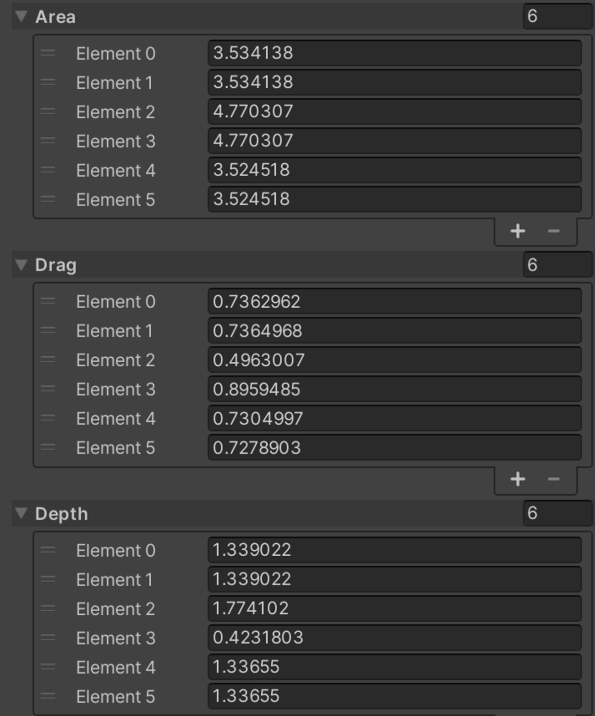
Drag cube data for the Size M conical command pod
So, a single drag cube is good for a part in isolation, but for a part that's attached to other parts, we need to determine how much of the part is actually exposed to the air (and eventually the airflow). That's the truly relevant part for calculating drag. Parts that are fully occluded by another part should effectively be invisible to airflow from that direction. You can think of this if you consider a fuel tank behind a cockpit traveling towards the pointy end of the vessel. If that assembly of parts is flying through the air, there should be no drag from the surfaces that connect the two parts.
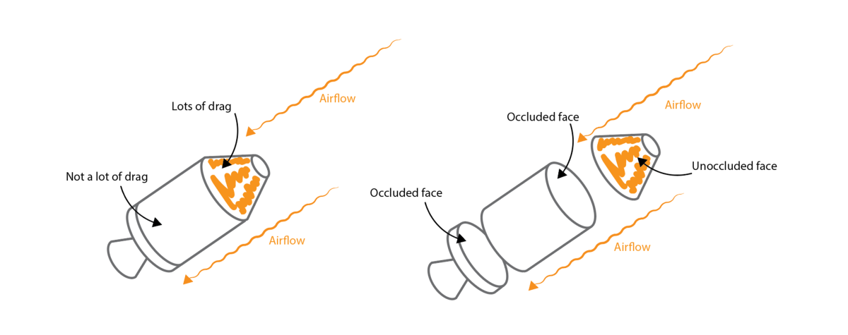
Schematic example of how we'd expect a vessel made of 3 parts to behave with respect to the occlusion of each of its faces
To calculate this occlusion, we use the area component of both parts' drag cubes, which can give us the area of parts from various directions. Take two parts from the above image, Part 1 (the fuel tank) and Part 2 (the command pod), that are connected. We look at the connection direction and modify each part's drag cube areas. We subtract the area of Part 1 in the +Y direction from the area of Part 2 in the -Y. We do the same in the opposite direction subtract the area of Part 2 in the -Y direction from the area of Part 1 in the +Y direction. This gives us a very simple way of approximating occlusion. If both parts are Size S, for example, the area through the connection becomes zero. If one part is Size S and one part is Size M, the Size S part will be completely shielded by the size M part, but the reverse is not true.
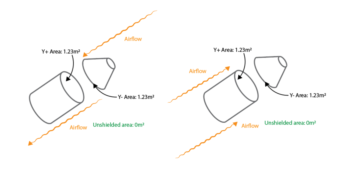
Schematic example of subtracting drag cube Y+ and Y- faces for same-size parts, in two airflow directions
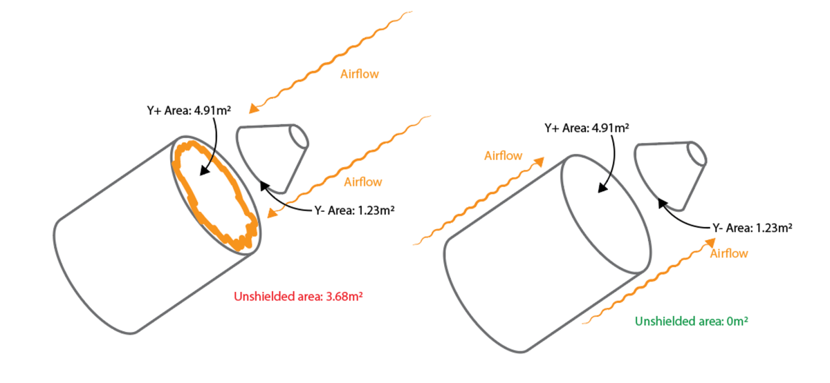
Schematic example of subtracting drag cube Y+ and Y- faces for different-size parts, in two airflow directions
I think that’s what you need to know about the basics of drag and occlusion. On to the bug!
We had community reports that were replicated by internal QA that some parts, like stacked decouplers, were affecting the aerodynamic performance of planes and creating too much drag. Planes that seemed like they should go fast went… slow. Exciting stuff - it's time for a bug hunt.
If adding a part to a plane creates too much drag, maybe that part itself has too much drag. We have tools to automatically create drag cubes, and sometimes we tune them manually. That's the first point of investigation for the team. Looking specifically at per-part drag readouts, we didn't find that the parts described in the bugs had any kind of anomalous drag values in isolation. Things looked in-line with what we’d expect. In addition, we couldn't reproduce these issues with rockets. This issue only really showed up when looking at planes. Planes are frustrating for me as a developer as I'm a garbage pilot and reproducing airspeed/velocity conditions reported in bugs takes me quite a while! That KSP2 pause button sure is useful…
So, eliminating general drag as a problem was a good first step. The next step would be identifying whether something was wrong with the occlusion system - but only for very specific parts. Hmm. Some of the specific parts identified were visually hollow tubes. Hollow tubes are a challenge for the drag occlusion system. Reading through my quick description of occlusion above, you might be able to see why, but let’s get into that.
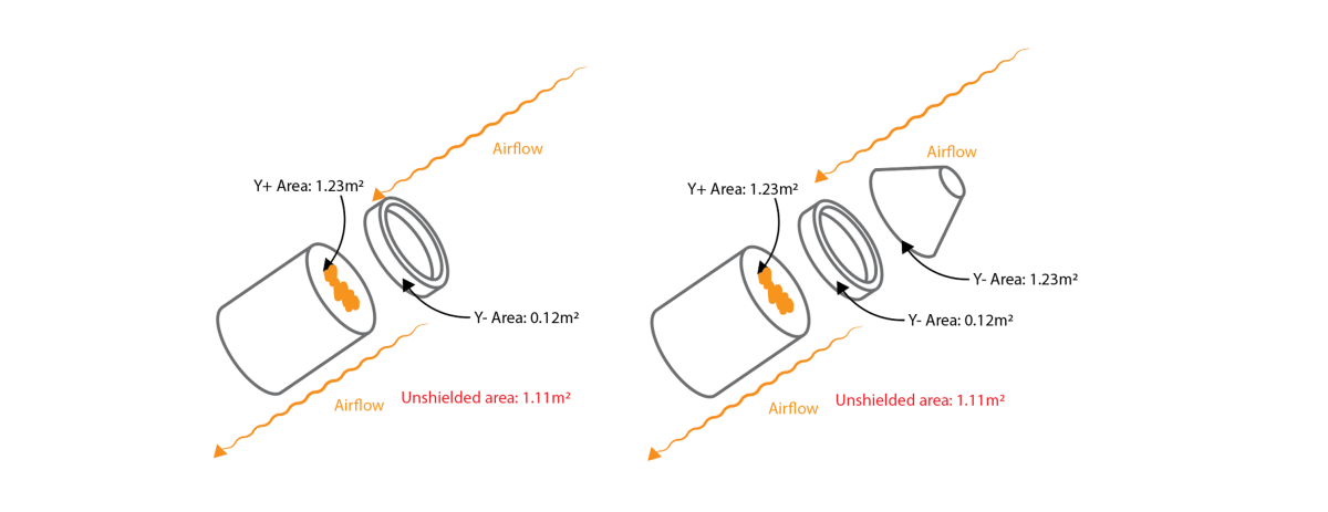
How a hollow part behaves by default in the KSP2 drag model to show how it doesn’t appropriately occlude the part below it
The drag cubes for hollow parts are, well, hollow by default! When we go to subtract the cross-sectional areas in a connection, the hollow part has a tiny cross-sectional area, and so won't appropriately shield the next part in the stack. This is fine if the hollow part is first, but if it is in a stack with something else atop it, we want it to occlude properly.
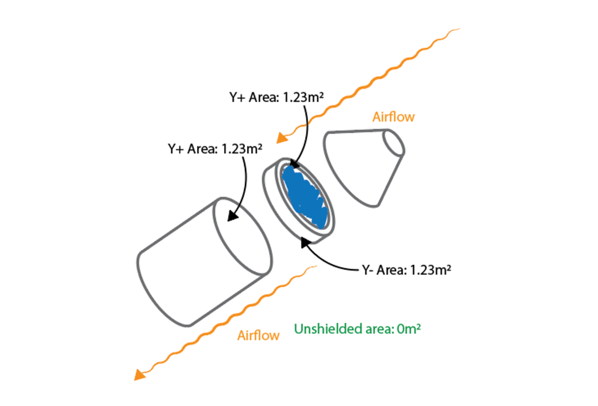
“Filling in” hollow parts to allow them to shield parts behind them
We solve this in KSP2 by manually adjusting the drag cube areas of hollow parts: they appear opaque in cross section and so subtract appropriately. It's a dirty fix, but it works.
So, decouplers are hollow. Some of the other parts reported with this bug are hollow. IDEA. Perhaps it's our process for manually adjusting this for those specific parts that is causing the problem. This caused a multi-day Chris wild goose chase of frustration and tweaking tiny numbers to no real solution. A clever reader might also realize something from the initial report that makes this avenue of investigation kinda silly in hindsight - if this was the problem, we should have seen this with rockets too, not just planes.
Eventually while examining the results of the wild goose chase, we looked specifically at the cross-sectional areas used for calculating occlusion and noticed an "interesting" discrepancy when considering certain parts. Let's look at this closely:
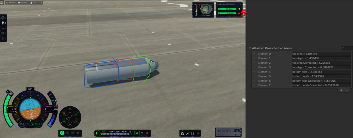
In this image you get to experience some internally famous ‘Chris paintovers’, terrible MS paint scrawls trying desperately to get a point across.
In the above image, I debugged the cross-sectional area for all the part connections on a demo ‘plane’. I noticed that the cross-sectional areas for the green and red highlighted parts were a little off. When looking at the green part, the game thinks that it has a cross sectional area of 1.19m2. This is… close to what it should be. But these parts have a radius of 0.625m2. That number should be closer to 1.23m2. Suspicious. The real problem is evident by looking at the blue part. The game thinks it has a cross sectional area of 2.38m2. That is far too much area - again, it should be 1.23m2. This provided a reasonable area of investigation. I tried the same approach but with one of the problematic parts from the bug report - the size S decoupler.
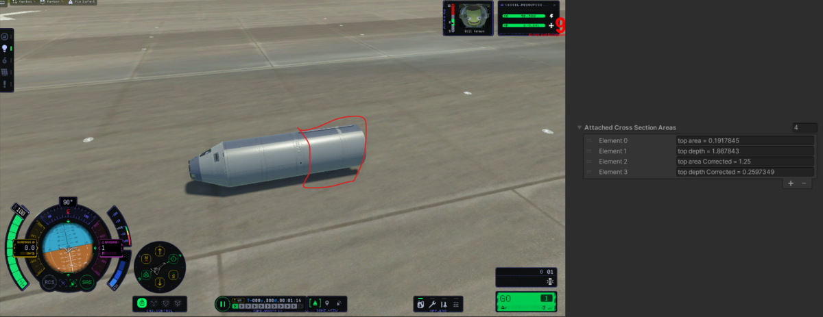
More live occlusion values
Well, this is just plain wrong. The game thinks this connection between the decoupler and tank (in red) has a cross sectional area of 0.191 m2. Jackpot! If this area is wrong, then the fuel tank 'behind' the decoupler will not be correctly shielded at all from airflow - the game thinks there's only 0.191m2 occluding the tank's cross-sectional area of 1.23m2. If this 'plane' flies forward, the game will act like there's a 1.03m2 blunt front-fuel tank surface into the airstream and create significantly more drag.
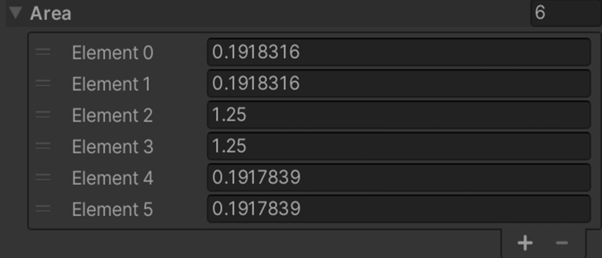
Drag Cube areas for the Size S decoupler
Ok, great. So where's the problem? Well, let's look at the drag cube for the Size S decoupler. Any of those elements look familiar? The first two and last two numbers are the area from the top, bottom, right and left of the part. The middle two entries (front/back) should be the ones we're using for the decoupler - but we're actually using the bottom two. Nailed it down - that's the core of the bug.
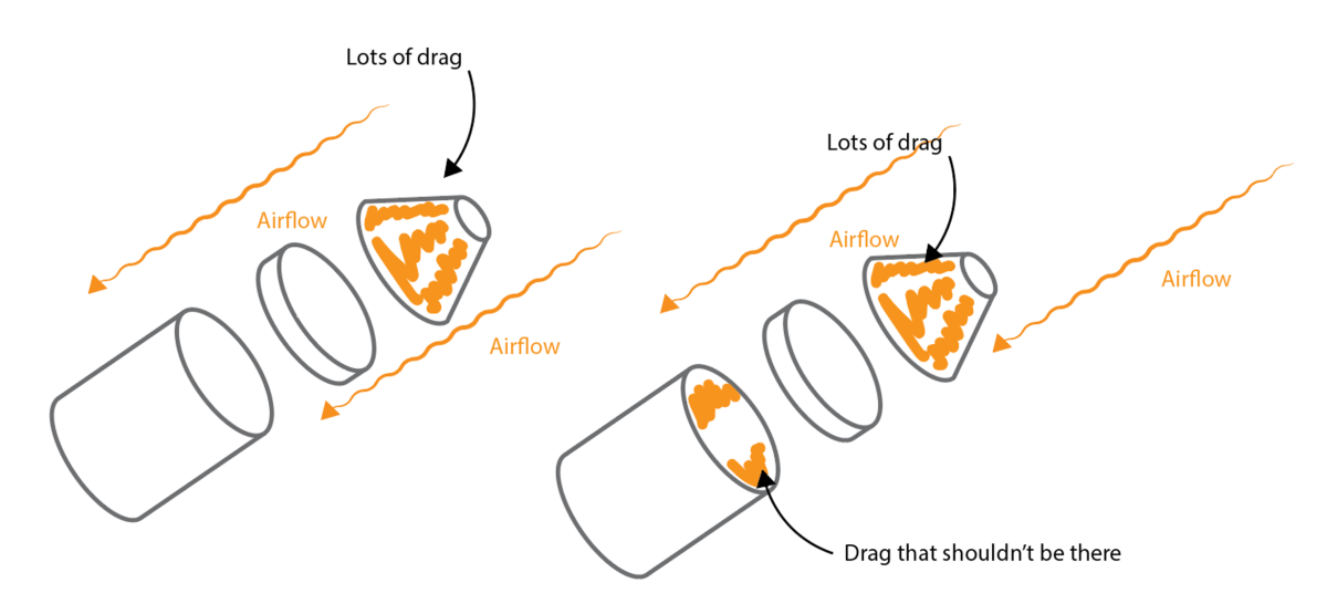
What we’d expect for post-occlusion drag (left) versus what we were getting (right)
It turns out that when we calculate cross-sectional area in craft orientations that aren't purely vertical (like planes) we calculate drag occlusion incorrectly - we use the wrong face of the attached part's drag cube. This has pretty strong implications that depend on the length and size of the parts you'd use in a plane's stack.
If a long part was in front of a short part, everything would appear fine. We'd be using the ‘side view’ of the long part with a large area, and that would be pretty good at occluding stuff (though actually TOO good). However, if you had a short part in front, additional drag would be introduced - not only because you'd not be occluding properly, but because that un-occluded area would be very un-aerodynamic!

A silly example of what we’d see (left) versus what the occlusion model would see (right). In this case you get too much drag, because there’s not enough occlusion

A second example of what we’d see (left) versus what the occlusion model would see (right). In this case you actually don’t get as much drag, because that Mk2 tank is occluding the Mk3 tank too much
That's enough information for an engineer to develop a fix. In this case, the fix for the issue only needed 2 lines of code, which was great. Identifying the issue and narrowing down the exact cause was the harder part of this bug.
Now, this isn't to say that drag issues are all solved in KSP2. But hopefully this provides a nice little tidy look at the somewhat messy process of going from a bug spotted by an eagle-eyed community member all the way to something we can fix.
