Developer Insights #11 – Engine Exhaust Visual Effects
Hey! I’m Jon Cioletti, the technical artist on KSP2. As a tech artist, it is my job to help merge the work done by artists into the more technical side of the project, to assist artists by making tools, and to write shaders for our game assets.
The most satisfying challenge of my work is that everything we make is driven by scientific accuracy. Whether it’s the lighting or the VFX, we want to be able to point at something happening in game and have a real reason behind why it appears the way it does. One of the best features to showcase this is with our engine exhaust visual effects.
Now buckle up, because the rest of this blog will now be me trying to summarize the lengthy creative process for engine VFX into like a 7 min read. Wish me luck.
Setting our goals
Step one for any concept investigation work starts with looking at cool images for reference and trying to decide what you want out of a feature. Many conversations occur at the design / art level well before it even gets to me in the pipeline. It’s in this time that people like Nate Simpson, Aaron Lundquist, and Dr. Michael Dodd discuss what our goals are for the effect and what scientific requirements it has.
For example, a major driving factor in the exhaust for us is pressure regimes. Pressure regimes roughly fall into three categories: sea level, transitional, and vacuum. We can create mockups for each of these states, then blend between them to create a more realistic depiction of exhaust. From this we can break down other aspects of the exhaust (color, shock diamond, heat distortion) and track them throughout the change in pressure. As seen in Nate’s diagram below, we already have the shape language of our effect planned out early in the process.

The first in-engine preview
Once the initial conceptual investigation is complete, we move down the pipeline to the art and VFX investigation of the effect. It’s here that we take the concepts and visual reference and start reproducing it in engine.
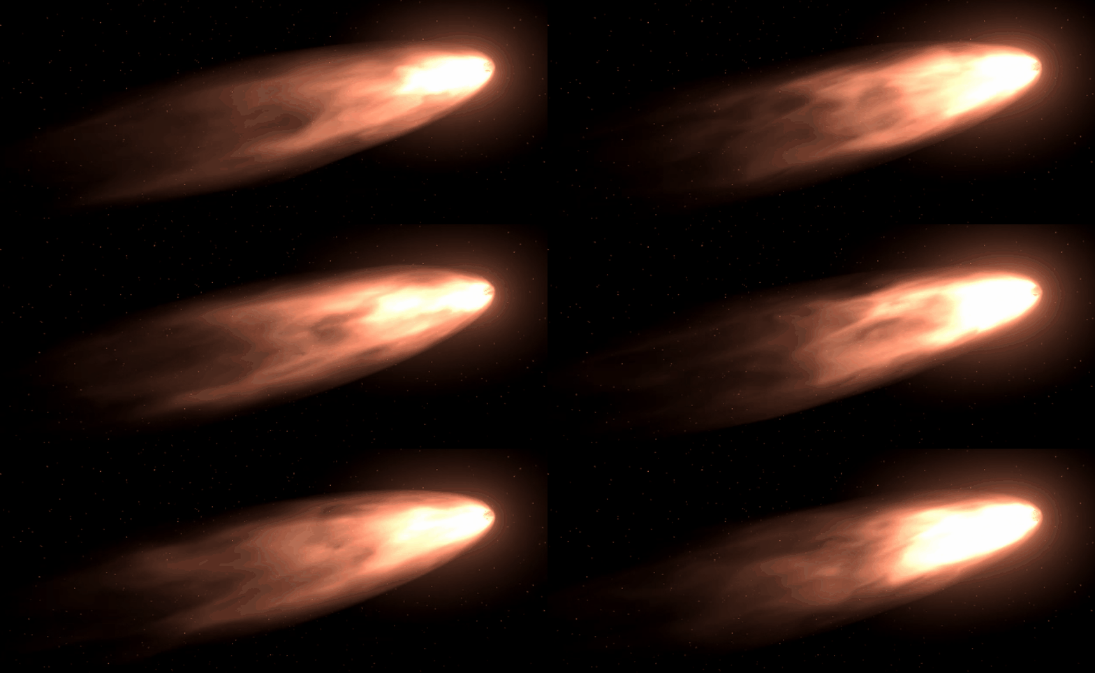
Below is work by Aaron Lundquist to create some initial looks at exhaust using scrolling textures, alpha masking, some vertex displacement and a nice dash of bloom to get that great glow.

Here we can see how the combination of textures can create a stunning effect

And here it is in motion
Taking a look at the Tech!
VFX Throttle ManagerMost of our tech for the engine exhaust is driven by that engine’s throttle and the air pressure at a given location in the universe. As we increase our throttle the exhaust
elongates, shows signs of speeding up and glows brighter with the increase of heat. The location in the universe is responsible for our transitions through pressure regimes. As an engine moves through different spaces, the exhaust will distort and tint to differ colors. To pass this data we need a component on the engine object in game. This component will collect the proper exhaust data values and send it off to our meshes, and materials.
Script based mesh scaling
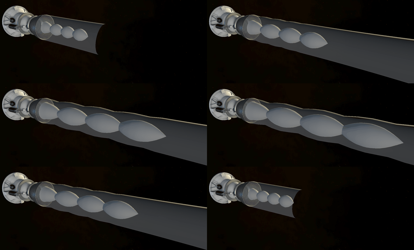
One part the Throttle Manager handles is the scaling of the exhaust’s shock diamonds. As the engine’s throttle increases, we scale the mesh for the diamonds larger and longer in accordance with the reference footage and diagrams we collected during our research phase.

Scaling of shock diamonds
BlendShapes
The Throttle Manager also controls the blending of our BlendShapes. To maintain our shape language established in the concept phases, we chose to work with BlendShapes, a technique used frequently in games for interpolating meshes. Below showcases some of that work in action thanks to renowned Kerbothropologist Paul Zimmer.

BlendShape models for blending

BlendShapes blending based on throttle and pressure Materials and Shaders
Simple hierarchy for models
The last thing our Throttle Manager passes data to is our effect’s material and shader. It’s here that we start modifying the actual look of the mesh itself so that it resembles something like the chemical reaction we see when an engine fires off. It’s also at this phase that we finally reach the place in the pipeline where I do my work on the effect.
“But Jon, what’s a shader?”
I’m glad you asked!
To boil it down to the bare essentials, a shader is a program that runs on the GPU that basically answers the question: “What color is this pixel when it is rendered to the screen?”. Like I mentioned above, it’s how we give things like the BlendShape and shock diamond meshes their exhaust look.
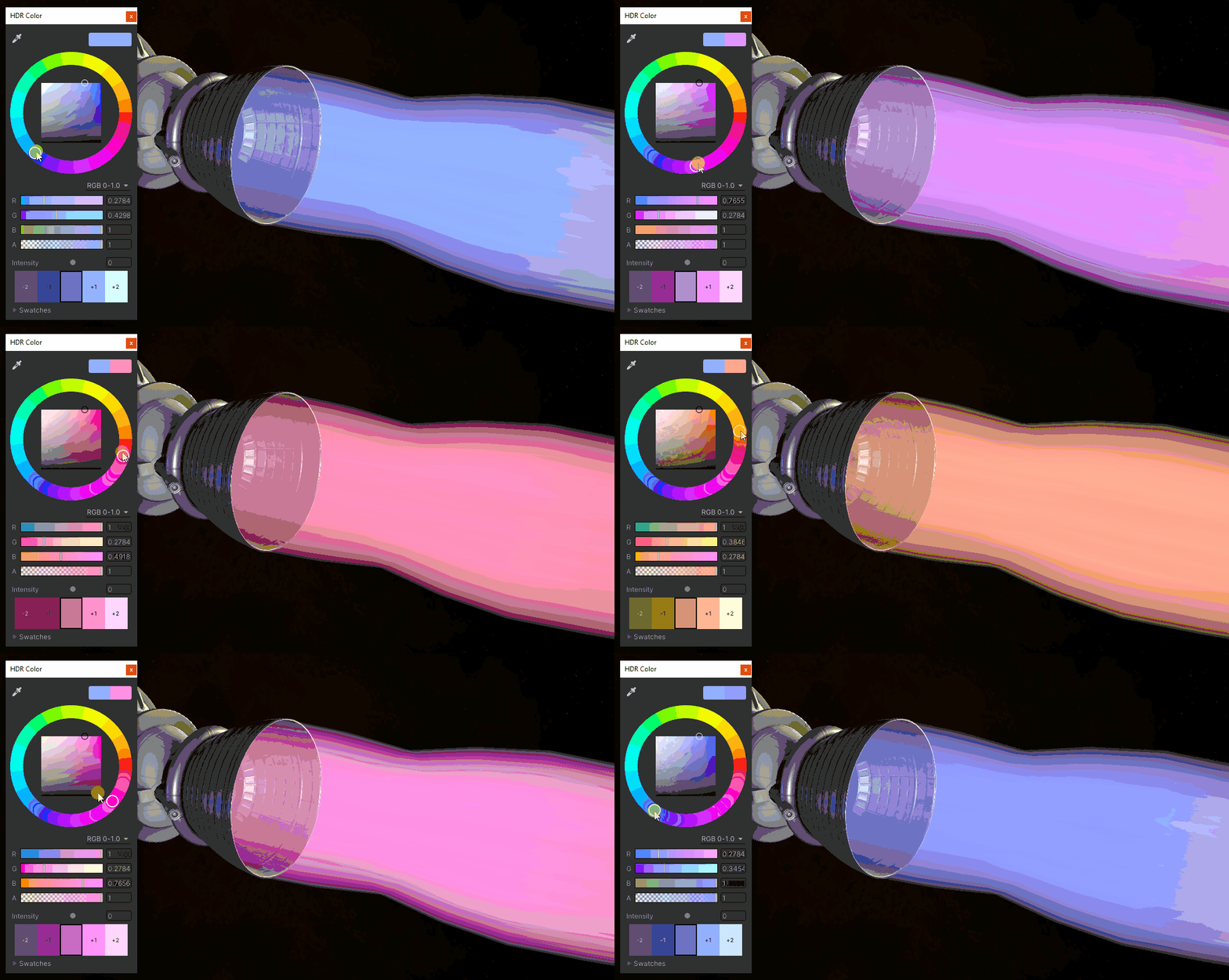
Every 3D model that we want to see in game needs a Material. Each material contains both the shader and the values we pass to it to modify it’s look. By passing in different values to our shader, we can create a wide range of exhaust materials for our different exhaust types. It’s pretty powerful stuff.
On the inside a shader can also be broken down into a few major parts. On the top we have its properties. “What values from the shader do we want to expose to the artist or code to modify?”. Colors, textures, numbers, and vectors are all valid inputs. Next is the vertex function. This is the first pass the geometry faces and is responsible for the altering of the 3D model’s vertices. While the BlendShapes modify the general structure, the vertex function lets us add things like a rumbling offset. Once through, the mesh’s triangle data then heads to the fragment function to receive their final colors. It’s here where our lighting and final surface look is calculated.

Example of modifying the Material’s color to get a different exhaust look
All together now
Okay, now for the big diagram. Below shows the data flow mentioned at the start of this section. Here is the basic flow:
The engine part’s Throttle Manager collects the data it needs from the game and uses it to calculate the exhaust data that needs to be passed along to the 3D mesh and material
The exhaust data scales or blends the shock diamonds and BlendShapes
The exhaust data is passed to the shader’s properties
Once in the shader it runs through the vertex function. The data modifies our exhaust’s shape to simulate turbulence and bends under acceleration
Next passing through the fragment shader, it receives its color gradient tinting, a scrolling noise to break up the gradient, an erosion alpha mask at the tail end, fresnels to soften up the edges and exit traces
Once through this process, the render pipeline renders the final effect to screen. And that’s just a single frame!

Getting the tech into the artist’s hands
Hey you made it this far! Your reward is the same as ours after this process, some sweet engine exhaust effects. With all these tools in place we can let Aaron loose on creating some amazing exhaust effects. This only covers the exhaust itself, there are still additional lighting and particle effects that need to be added. Enjoy!
