Developer Insights #12 – Planet Tech
Hi, I’m Eric DeFelice, a graphics engineer on the KSP2 team. My job is to create technical solutions to the graphics features we have on KSP2. One of the most obvious of these systems is how we generate, position, and render the planets in the game.
We need a system to render the planets while in orbit and interstellar travel, as well as up close, on the planet surface. We want transition between these distances to appear as you would expect, as you get closer to the planet surface, you just see more detail. How do we solve all the problems associated with a graphics feature such as this? Can we just use traditional approaches for level of detail?
Lets dive a bit deeper into how we solve this problem in KSP2. I’ll try to give as much detail as I can without having this take an hour to read…
Basic mesh rendering & LOD systems
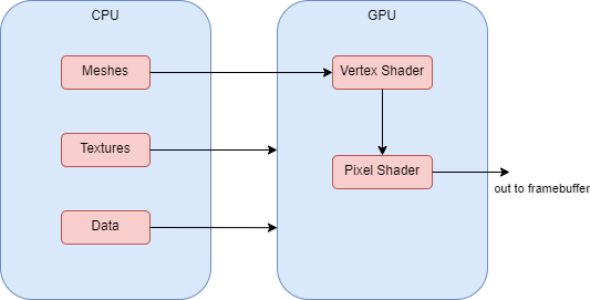
Lets start by looking at how most meshes are rendered in KSP2 (and most games for that matter). Generally, the mesh data is sent from system memory over to the GPU, where shaders read it, place it at the correct pixels on screen and output the correct color given some material properties. We could try and use this approach for our planets, but there are a couple big issues we would have when trying to achieve the level of detail we would like.

The biggest issues we would have revolve around the memory usage that it would take to store all that vertex data for planets that are as large and detailed as we have in the game. We could mitigate these problems with level of detail approaches, and perhaps trying to break up the planet into chunks, so we could only load in the chucks that are relevant. GPU tessellation is also a possibility, but that wouldn’t really give us much control over the terrain height. One other big issue has to deal with the size of our planets and precision issues when trying to position the planet in camera projection space. I’ll talk more about this shortly.
Given these problems, we don’t use this basic approach when rendering planets up close. We do however use this basic approach when rendering planets from further away. This allows artists to have full control over the look of the planet from this distance, and is a good starting point to add more detail to as you approach the planet surface.
Planet Positioning
Another core gameplay feature we have to keep in mind when rendering the planets is that their position may be moved around relative to our floating origin (for more info, see the previous dev blog by Michael Dodd). For our planet rendering purposes, this means that our planet center will usually be further from the origin than its radius. If we defined the planet vertex data in model space, then during rendering, when we transformed its position to camera projection space, we could possibly be dealing with some large transformation values. If we then are viewing the terrain while it is close to the camera, creating very small distances in camera space, we may have some visual artifacts (as seen above).
How do we deal with this possible problem? Well, one simple solution is to generate the vertex data so it is relative to the floating origin already. That way we don’t have to deal with the model to world transformation, keeping the position values in a reasonable range.
So now that we have our key concerns listed, we can finally look at how we solved these problems in KSP2.
PQS System Overview for KSP2
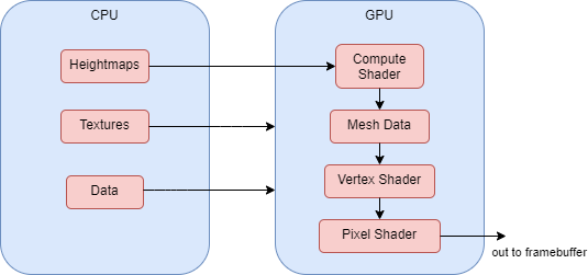
In KSP2 we use a very similar PQS (procedural quad sphere system) that was used in KSP1 (here is much more detail in the basics of that system). We have made some updates to the system, namely that we now generate all of the planet mesh data in compute shaders. This planet vertex data never gets sent back to the CPU, and we just send a procedural draw call to the GPU to render the mesh with the compute buffer data.

We do determine quad sub-divisions in a similar way as KSP1, but we generate the output mesh positions relative to our floating origin, instead of relative to planet center. When calculating each vertex position, we also calculate the height, slope and cavity for the mesh so that we can perform procedural texturing in the planet shader. One caveat we needed to account for in our procedural parameter calculation is that we need to make sure we have stable values for any given position on a planet. This is needed because we don’t want the texturing to visually change at a given position, which could occur if the slope changes at that position because of mesh tessellation.
For tessellation, we have to balance the level of detail we want at various distances with the performance concerns of generating more vertex data. The goal is to bump the level of detail for the terrain at a distance that isn’t really noticeable, so we don’t have a ton of visual detail popping in. We are constantly improving in this area (for reference, here is some previous footage of our planet tessellation tech).
One other feature we have to help improve performance is basic frustum culling. Since we don’t have a bunch of mesh data on the CPU we can’t rely on traditional approaches for culling, so we have to do this on our own. Since we already have a bunch of quad data, we might as well just use their positions for this purpose. On the CPU we can determine which quads are within the camera frustum, and only generate visual mesh data for those. This prevents us from doing a bunch of work on the GPU that we know will be thrown away later, since that part of the mesh isn’t even visible.PQS Collider System Overview
Terrain colliders need to be created by this system as well, since they rely on the mesh data for the planet. There are a few differences in the requirements for collision however. We no longer want to tessellate collision mesh data based on distance from the camera, but rather on distance from possible colliders that could hit that terrain. Because of this, we need to keep track of separate collision quad data.
We also can’t perform the same frustum culling that we do for the visual mesh, as a vessel could be out of view when it collides with the terrain. Can we still do some sort of culling though? You guessed it, we can. We just cull any terrain colliders that we deem too far away to possibly have a collision in that frame. This does the same job as frustum culling does for the visual mesh, prevents us from doing a bunch of work on the GPU that we know is useless.
Everything coming together
Hopefully I gave you some more insight into how we generate and render our planets in KSP2. The key goals of the system are to provide a high level of detail of the planet at all distances while maintaining a solid frame rate. There are many unique problems in KSP2 compared to most other games I’ve worked on, so we definitely had to get creative with our solutions.
One final tidbit I’ll leave you with, is our system for how we transition to our PQS generated mesh from the low LOD mesh. Borrowing a technique from basic LOD systems, we actually just perform a cross-fade dither between the two meshes.
